
Installation instructions
Seemoto System Equipment Setup and Installation Instructions
Sensors
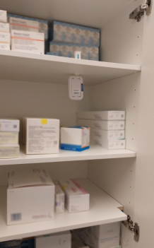
TS Room temperature and THS
- Sensors must be positioned so that there are no products or other obstacles in front of them. Sensors should be visible and attached/positioned so that they are not hidden behind shelves, for example.
- The sensor must not be attached to metal and should be in an upright position with its front side (Seemoto sticker) facing the base station, room doorway, or open space.
- It is best to install the sensor slightly higher, but not higher than the doorway, for example.
TS Refrigerator
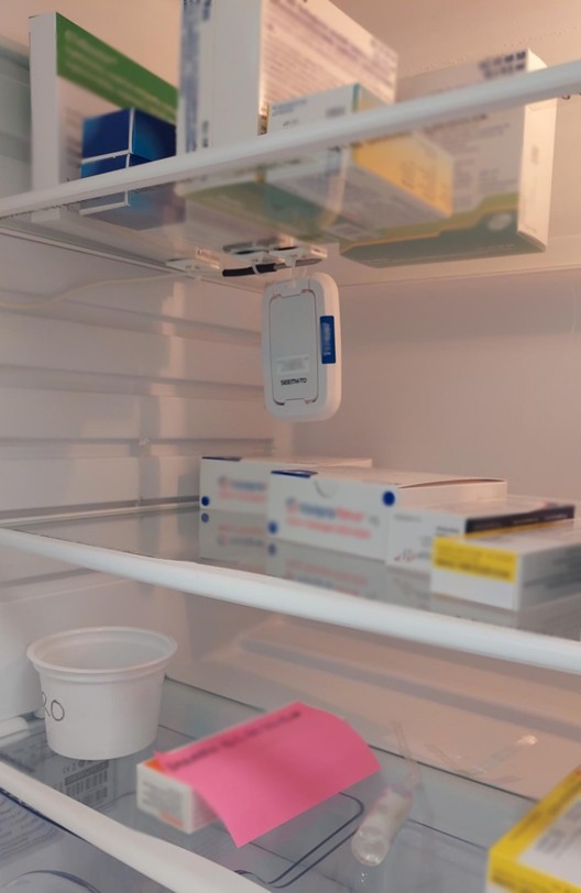
- The sensors should be placed on the second shelf from the top of the cabinet, at the front of the shelf, in an upright position. The sensor must not touch any products, so that the temperature reading is not distorted. Leave a few centimeters of free space around the sensor.
- The sensor can, for example, be hung from a shelf grid using a cable tie or alternatively placed in a plastic container so that the sensor is in an upright position.
- In a cabinet with drawers, the sensor can be attached vertically to the plastic partition using the adhesive backing on the back plate, as high as possible.
- The sensor must not be attached to the walls of the cabinet, nor should it be horizontal or in contact with metal.
- The sensor should be positioned so that the front of the sensor (Seemoto logo) faces outwards from the cabinet.
- If the refrigerator is recessed into the wall, pull the cabinet outwards so that the door seals are visible when viewed from the side. If there are three cabinets side by side, for example, pull the middle one out slightly so that its door seals are also visible when viewed from the side.
TS Vehicle
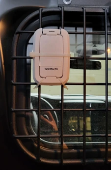
The wireless Seemoto sensor consists of two parts: the sensor itself and the backing plate.
- The backing plate activates the sensor. Without the backing plate, the sensor does not measure.
- The backing plate is also used for installing/mounting the sensor.
- The power light flashes once in the upper right corner of the front panel within 60 seconds of attaching/detaching the backplate.
The sensor installation location is selected based on the customer's instructions. If no specific instructions are provided, the sensor is installed in the cargo compartment as follows:
- The backing plate/sensor must not be in contact with metal, in the airflow of a heating or cooling device, or in the immediate vicinity of a door.
- The installation location should be chosen so that the sensor is not exposed to impacts and does not interfere with normal vehicle use.
- First, place the lower part of the sensor in position and then press the upper part of the sensor onto the backing plate. The sensor will click into place.
- This ensures that the sensor will not detach from the backing plate under any circumstances.
TS-PT Installation Instructions
Getting started
Before installation/use, make sure that the package contains the following devices and accessories:
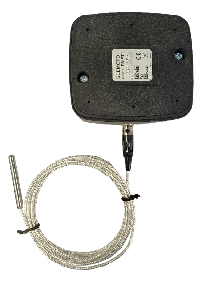
- TSPT device
- Sensor probe
Installation/Operation
Do not install the device directly against metal surfaces or surrounded by metal.
Activating the device
The device is delivered with the battery disconnected. The battery must be connected before use.
Connecting the sensor probe
Ensure that the sensor probe is properly connected to the corresponding connector.
Do not switch sensor probes between different measuring units or terminals.
Device installation
Place the device in a safe location where the probe can reach the unit to be monitored.
Avoid placing the device against metal surfaces and protect it from water, moisture, and high humidity.
It is recommended that the device be securely fastened in place with Velcro.
TS-Logger Installation Instructions
These instructions describe how to use the transport logger when shipping and receiving temperature-controlled transport boxes.
Shipping of temperature-controlled boxes
If a measurement start delay has been programmed for the logger, temperatures will only be recorded after the delay has expired.
Receipt of temperature-controlled box
- Green indicator light: The limit values have been maintained during transport. The limit values are marked on the sticker on the logger.
- Red indicator light: The limit values were not maintained during transport. Do not unpack the shipment before checking the operating instructions.
The transport logger automatically downloads the measurements to the Seemoto service when it is brought close to a Seemoto base station. The transport logger switch does not need to be turned on for the measurements to be downloaded.
IAQS without pressure difference
Before installation, check that the sales package contains the following devices and accessories:
- Indoor air quality monitor (IAQS)
- Wall bracket for measuring device
- Stickers for fastening
- Power supply
Installation of IAQS measuring device
- Install the device at a height of approximately 1.5 meters above the floor.
- If possible, install the device in a central location in the room. For practical reasons, the device is often mounted on a wall, in which case you should avoid installing it near doors and/or windows.
- Consider the immediate environmental factors when positioning the device; for example, in a school classroom, the device should be installed in a location where it does not attract too much attention.
- Connect the power supply's Micro-USB connector to the indoor air quality monitor.
- Plug the power supply into a power outlet.
The device is now installed without pressure difference measurement.
IAQS pressure difference
IAQS - Indoor air quality sensor using pressure differential measurement
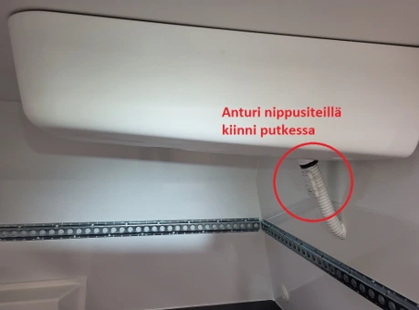
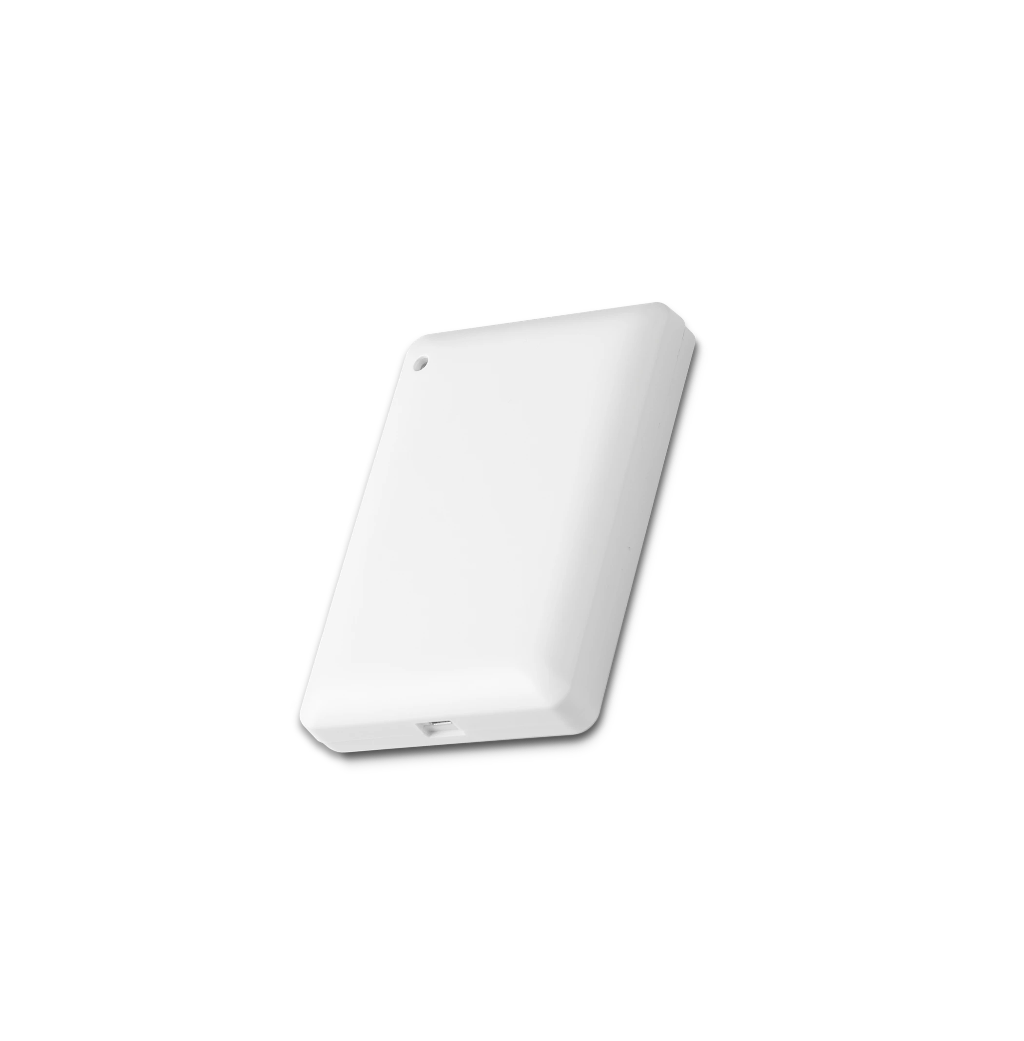
The IAQS sensor with pressure difference measurement measures not only normal air quality parameters but also the air pressure difference between indoor and outdoor spaces. This is particularly important when monitoring clean rooms in pharmacies or other special facilities, for example.
Installation steps (with pressure differential measurement)
- Drill a 6-8 mm hole in the outer wall or window frame.
- Install the supplied copper pipe (feed-through) into the hole so that it extends to the outside.
- Seal the gap between the copper pipe and the wall/window frame completely airtight with silicone or acrylic sealant.
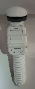
- Connect the pressure difference measurement hose to the copper pipe so that the hose is tightly attached but does not bend too much.
- Install a weather guard on the outside of the hose to prevent water and insects from entering the hose.
Points to Note When Measuring Pressure Differences
- The pressure difference measurement accuracy is ±0.5 Pascal (Pa), which is sufficient for most monitoring purposes.
- The measuring hose must not be kinked or pinched at any point.
- Ensure that the measurement point on the outside is not exposed to strong winds, which could distort the measurement result.
- Regularly check that the feed-through is still tight and that there are no blockages in the hose.
- If the pressure difference in the space changes suddenly, first check the condition of the measuring hose and the tightness of the feed-through.
Base stations
WGW Installation Instructions (Basic)
Installation of a WGW base station
When installing the base station, please note the following
- The base station should be installed in a location with the best possible line of sight to the sensors.
- Do not install the device directly against a metal surface. A minimum distance of 5 cm from the metal surface is recommended.
- If possible, install the device at a height of approximately 180-220 cm from the floor.
- Do not install the device directly on the ceiling.
- The device must have the best possible visibility to the sensors so that their signals can travel unimpeded. If there are sensors in several rooms, try to install the base station so that it has the best possible coverage of all rooms.
- Please note that signal transmission through walls is weakened, especially through concrete walls. If necessary, use a signal booster (REV device).
The base station is delivered pre-configured and automatically starts searching for a network connection and sensor signals as soon as it is powered up.
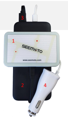
WGW power bank
Installing a WGW base station in a vehicle using a power bank
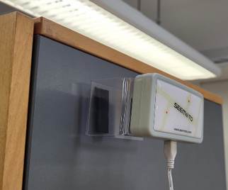
When using the base station in a vehicle or other location where a continuous power supply is not available, a power bank can be used as a power source.
Using a power bank
Please note
- Do not leave the power bank or base station in the vehicle for long periods in extremely cold (below -10°C) or hot (above +40°C) conditions.
- Check the power bank's charge regularly and recharge it if necessary.
- The base station indicates its operation with a red LED light that flashes regularly when the device is turned on.
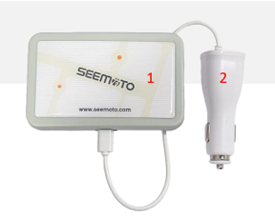
WGW car charger
Installing a WGW base station in a vehicle using a car charger
The base station can be used in a vehicle while continuously connected to the car charger, in which case it is powered when the vehicle is running.
Car Charger Installation
Please note
- The car charger does not supply power to the base station when the vehicle is not running, unless the vehicle's power outlet is continuously powered.
- If temperature control during transport is critical even when the vehicle is turned off, use a power bank or ensure that the vehicle's power outlet is constantly powered.
- The base station automatically uploads the stored measurement data to the internet when it is connected to a mobile network.
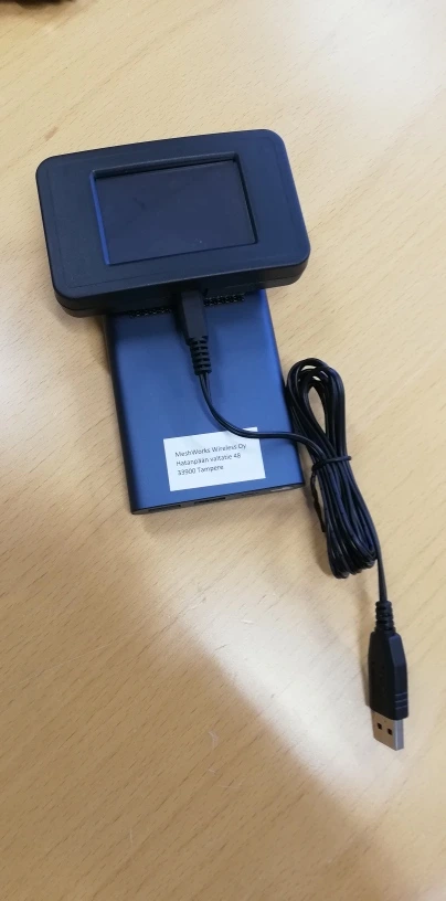
DGW power bank
Installation of the DGW display base station with a power bank
The DGW base station is designed for visualizing temperature measurements on a display. When operating with a power bank, it can be installed in various locations that are essential for its use.
Installation steps
Please note
- The duration of a power bank depends on its capacity and screen brightness. Typically, a 10,000 mAh power bank provides approximately 20-30 hours of use.
- Ensure that the device has a good connection to the base station and sensors.
- The brightness of the display should be adjusted according to the operating environment to achieve optimal visibility and power consumption.
- Regularly check the charge status of the power bank and replace it with a charged one if necessary.
DGW without power bank
Installing the DGW display base station using mains power
The DGW base station can also be permanently installed to use mains power, which is recommended for permanent installations.
Installation steps
Please note
- Ensure that the power cord is positioned safely and does not pose a tripping hazard.
- Position the device so that air can circulate around it and it does not overheat.
- If no measurement data appears on the display within a few minutes of startup, check that the base station and sensors are turned on and functioning properly.
- After a prolonged power outage, the device will automatically restart when power is restored.
EGW Installation Instructions
Installing the EGW Ethernet Access Point
EGW is a base station that connects to the Internet via a network cable (Ethernet) and is designed for fixed installation. It is the optimal solution for locations with a reliable fixed network connection.
Installation steps
- High location (recommended height 180-220 cm from floor level), but not directly attached to the ceiling.
- No metal surfaces near the device; maintain a distance of at least 5 cm from metal structures.
- Good visibility to sensors, not behind shelves or cabinets.
- Within the range of the network cable, close to the network connection point (RJ45 plug).
Implementation and Operation
Please note
- If the LED indicator does not turn solid green within 30 minutes, check the network cable connection and network functionality.
- The EGW base station requires a DHCP server on the network for automatic IP address retrieval. Static IP addresses are not supported in the basic installation.
- The device operates automatically after restarting and does not require separate configuration.
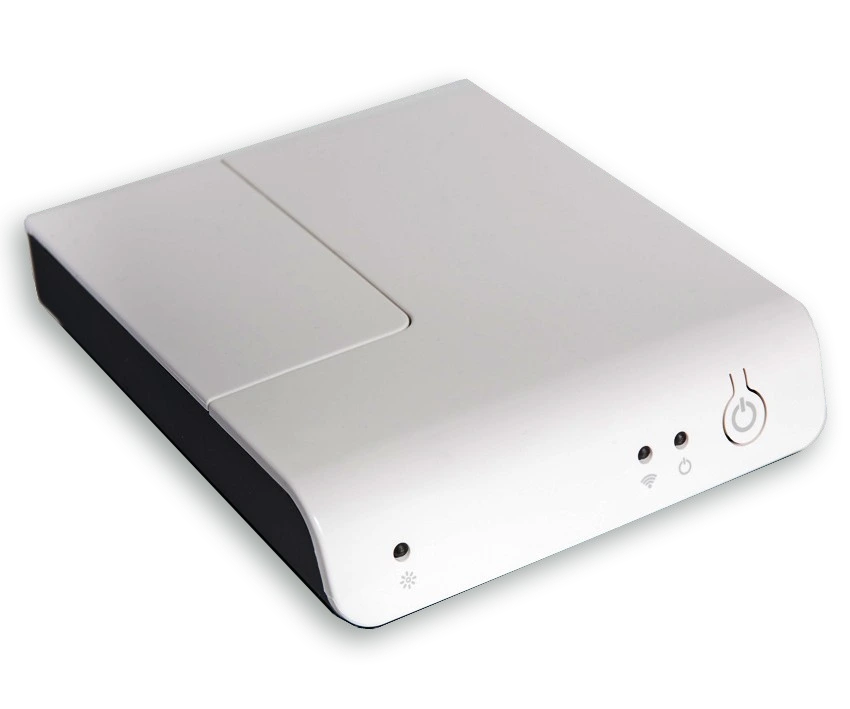
Routers
REV Installation Instructions
Installation and Use of the REV Signal Amplifier
REV (Range Extender) is a signal amplifier that extends the range of the sensor network. It is placed between the base station and the sensors in locations where direct signal transmission is weak or completely blocked. Such locations include other rooms, floors, or buildings.
Basic Principles of Investing
Installation steps
- High location, as with base stations (recommended 180-220 cm above floor level).
- Not directly against metal or near metal walls.
- Close to a power outlet, as the REV requires a constant power supply.
- Securely fastened so that the device cannot fall.
Implementation and Operation
Please note
- REV always requires a continuous power supply to operate—a power failure will also interrupt signal amplification.
- Multiple REV devices can be installed in a single system to extend the signal in different directions.
- If the signal does not improve after installing the REV device, try moving the device closer to the sensors or base station.
- After a power failure, REV restarts automatically and does not require manual restarting.